
Effective Date: May 1, 2026
Summary: This standard establishes technical criteria for ground and foundation treatments using the Rapid Impact Compaction (RIC) method. It outlines comprehensive provisions regarding geotechnical design, layout patterns of impact points, specific on-site operation processes (such as dynamic monitoring of blow frequency and settlement), and strict post-compaction quality inspections. The standard aims to safely enhance ground bearing capacity for varied civil and industrial infrastructure projects.
China Association for Engineering Construction Standardization Standard
T/CECS 2103-2025
Chief Drafting Organizations: Shandong Mechanical Construction Co., Ltd. Shandong Jianzhu University
Approving Authority: China Association for Engineering Construction Standardization
Effective Date: May 1, 2026
China Planning Press 2025 Beijing
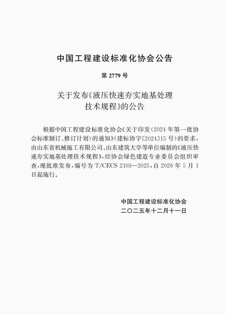
No. 2779
Announcement on the Publication of the Technical Specification for Rapid Hydraulic Compaction Ground Improvement
In accordance with the requirements of the Notice on the Printing and Distribution of the 2024 First Batch of Association Standards Development and Revision Plan (Jian Biao Xie Zi [2024] No. 15) of the China Association for Engineering Construction Standardization, the Technical Specification for Rapid Hydraulic Compaction Ground Improvement, drafted by Shandong Mechanical Construction Co., Ltd., Shandong Jianzhu University, and other organizations, has been reviewed and organized by the Green Construction Professional Committee of the Association, and is hereby approved for publication, designated as T/CECS 2103-2025, effective from May 1, 2026.
China Association for Engineering Construction Standardization
December 11, 2025
The Technical Specification for Rapid Hydraulic Compaction Ground Improvement (hereinafter referred to as the "Specification") has been prepared in accordance with the requirements of the Notice on the Printing and Distribution of the 2024 First Batch of Association Standards Development and Revision Plan (Jian Biao Xie Zi [2024] No. 15) of the China Association for Engineering Construction Standardization. The drafting committee conducted in-depth investigations and research, conscientiously summarized practical experience, referenced advanced domestic and international standards, and formulated this Specification on the basis of extensive solicitation of opinions.
This Specification consists of 6 chapters, mainly covering: General Provisions, Terminology, Basic Requirements, Design, Construction, and Quality Inspection.
Certain contents of this Specification may involve the use of patented technology related to A Method for Micro-Vibration Compaction Construction of Foundation Soil (Patent No.: ZL202311021292.2). Regarding specific technical issues involving the patent, users may directly negotiate with the patent holder (Shandong Mechanical Construction Co., Ltd.). Apart from the aforementioned patent, certain contents of this Specification may still involve other patents; the publishing organization of this Specification shall not bear the responsibility for identifying such patents.
This Specification is under the centralized management of the Green Construction Professional Committee of the China Association for Engineering Construction Standardization, and Shandong Mechanical Construction Co., Ltd. is responsible for the interpretation of specific technical contents. During implementation, any comments or suggestions shall be forwarded to Shandong Mechanical Construction Co., Ltd. (Address: Building 2, Sanjian Heping Plaza, No. 167 Jingsi Wei-Shi-Er Road, Huaiyin District, Jinan; Postal Code: 250021; Mobile: 18888297518; Email: sdjs1960@163.com).
Chief Drafting Organizations: Shandong Mechanical Construction Co., Ltd., Shandong Jianzhu University
Co-Drafting Organizations: Shanghai Geotechnical & Geological Research Institute Co., Ltd., Shandong Zhengyuan Environmental Technology Co., Ltd., Qingdao University of Technology, China Construction Eighth Engineering Division Second Construction Co., Ltd., Jinan Culture & Tourism Group Industrial Investment Co., Ltd., Tai'an Hengda Machinery Co., Ltd., China Construction Civil Engineering Co., Ltd., Jinan Jinnuo Highway Engineering Supervision Co., Ltd., Shandong Construction Engineering Quality Inspection & Testing Center Co., Ltd., Shandong Dingxin Geotechnical Technology Co., Ltd., Qingjian Group Co., Ltd. Jinan Branch, Inner Mongolia University, Civil Aviation Airport Planning and Design Research Institute Co., Ltd., North China University of Water Resources and Electric Power, Beijing Zhongyan Dadi Technology Co., Ltd., Jinan Transportation Engineering Quality and Safety Center, Jinan Rail Transit Group Co., Ltd.
Chief Drafters: Zhang Zhankui, Zhou Chong, Shen Bin, Zhang Sifeng, Wang Qingzhong, Li Ke, He Donglin, Liu Bo, He Xiliang, Liang Ruming, Guan Fei, Cui Chunlei, Liu Junwei, Feng Lingyun, Liu Tao, Li Jinxing, Bu Fadong, Yue Fansu, Li Qingjun, Li Jun, Wu Biao, Chang Jianmei, He Rong, Wang Yong, Xiao Fenggang, Chen Chongxin, Zhang Yi, Hao Dengpeng, Hou Zhongcheng, Wang Dehong, Guo Chunsheng, Li Hongwei, Sun Yonghua, Liu Zhixun, Liu Guangqing, Wang Teng, Ding Deli, Zhang Wenxing, Lu Liuying, He Peng
Chief Reviewers: Liu Junyan, Sun Jie, Gao Wensheng, Xin Gongfeng, Chen Degang, Chen Jian, Cui Shiqi
1.0.1 This Specification is formulated to regulate the application of rapid hydraulic compaction ground improvement technology, ensuring safety and applicability, reliable quality, advanced technology, economic rationality, and environmental protection.
1.0.2 This Specification is applicable to the design, construction, and quality inspection of rapid hydraulic compaction ground improvement for building and municipal infrastructure projects.
1.0.3 The application of rapid hydraulic compaction ground improvement technology shall comply not only with the provisions of this Specification but also with the provisions of current relevant national standards and current standards of the China Association for Engineering Construction Standardization.
2.0.1 Rapid Hydraulic Compaction (RHC)
A method of compacting foundation soil using a hydraulic impact hammer at a frequency of no less than 30 blows/min.
2.0.2 Effective Improvement Depth
The depth range within which the foundation soil, after rapid hydraulic compaction treatment, can meet the design requirements for physical and mechanical property indices.
2.0.3 Rated Impact Energy
The impact energy possessed by the hydraulic impact hammer when the hammer core is at its maximum stroke.
2.0.4 Single-Blow Impact Energy
The energy possessed by a single impact of the hydraulic impact hammer within the effective stroke range of the hammer core.
2.0.5 Number of Blows
The cumulative number of impacts applied to a single impact point continuously or in passes.
2.0.6 Number of Passes
The number of passes when adopting multi-pass compaction or staggered row/point compaction at impact points.
2.0.7 Average Compaction Settlement
The difference between the average elevation of the site before and after compaction.
2.0.8 Tamper Foot Diameter
The diameter of the anvil at the bottom of the hydraulic impact hammer that contacts the foundation soil.
2.0.9 Main Impact Point
The impact points with larger spacing in the first pass when adopting staggered row or staggered point multi-pass compaction.
2.0.10 Inserted Impact Point
The impact points located between the main impact points when adopting staggered row or staggered point multi-pass compaction.
2.0.11 Trial Compaction Zone
A representative test area selected within the project site prior to rapid hydraulic compaction construction, used to verify the applicability of construction parameters and treatment effectiveness.
3.0.1 The design and construction of rapid hydraulic compaction ground improvement shall follow the principles of using local materials, conserving resources, and protecting the environment. Construction parameters shall be reasonably determined based on geotechnical engineering investigation data, design requirements, construction site conditions, and surrounding environmental conditions. Information-based management and quality control during construction shall be strengthened.
3.0.2 Rapid hydraulic compaction is applicable for the treatment of miscellaneous fill, plain fill, gravelly soil, sandy soil, silty soil, silty clay, and collapsible loess foundations.
3.0.3 Prior to formulating a technical plan, the impact of construction operations on the surrounding environment shall be assessed. Rapid hydraulic compaction technology may only be adopted when the limited requirements for protected objects are met.
3.0.4 For saturated silty clay, coarse-grained cushion materials shall be used for replacement, or the construction method of filling materials into compaction pits shall be adopted. Replacement materials may include well-graded block stone, crushed stone, construction waste, and other hard coarse-grained materials, and the content of particles larger than 300mm should not exceed 30%. The replacement thickness shall be determined through trial compaction.
3.0.5 The groundwater level shall be at least 1.5m below the initial compaction surface. When this requirement is not met, dewatering measures shall be taken.
4.0.1 The calculation of bearing capacity and deformation of rapid hydraulic compaction treated ground shall comply with the relevant provisions of the current national standard Code for Design of Building Foundations GB 50007.
4.0.2 The construction scheme for rapid hydraulic compaction ground improvement shall be formulated based on the design requirements for foundation bearing capacity and effective improvement depth.
4.0.3 The applicability of the construction scheme, process parameters, and treatment effectiveness shall be verified through trial compaction, and the construction scheme and process parameters shall be optimized based on trial compaction results. The number of trial compaction zones shall be determined based on site complexity, building scale, and building type. Trial compaction zones shall be representative, and the area of each trial compaction zone shall be no less than 100m².
4.0.4 The point compaction energy shall be determined based on the improvement depth, foundation soil properties, and other conditions. The blanket compaction energy shall be 1/2 of the point compaction energy, and shall not be less than 36kJ.
4.0.5 The effective improvement depth of rapid hydraulic compaction treated ground shall be determined based on field trial compaction or local experience. In the absence of test data or experience, the values in Table 4.0.5 may be used for estimation.
Table 4.0.5 Estimated Effective Improvement Depth of Rapid Hydraulic Compaction Treated Ground
| Single-Blow Impact Energy (kJ) | Coarse-Grained Soil (m) | Fine-Grained Soil (m) |
|---|---|---|
| 36 | 1.5~2.0 | 1.2~1.5 |
| 60 | 2.0~3.0 | 1.5~2.5 |
| 84 | 3.0~4.0 | 2.5~3.5 |
| 108 | 4.0~5.0 | 3.5~4.5 |
| 150 | 5.0~6.5 | 4.5~6.0 |
Note: When the required treatment depth exceeds the equipment capacity, layered compaction shall be adopted.
4.0.6 The number of blows for point compaction shall comply with the following provisions:
1 According to the energy classification specified in Table 5.2.1 of this Specification, the average compaction settlement of the final 10 blows for light, medium, and heavy energy classes shall be controlled at 10mm, 20mm, and 30mm respectively;
2 When the ground improvement depth is not greater than 2.0m, the number of blows shall not be less than 30; when the improvement depth is greater than 2.0m, the number of blows shall be determined through field trial compaction and local construction experience;
3 The ground heave around the compaction pit shall not exceed 1/4 of the pit depth.
4.0.7 Depending on the shape of the foundation base, impact points may be arranged in equilateral triangular, isosceles triangular, or square patterns.
4.0.8 The point layout spacing shall be 1.5 to 2.0 times the tamper foot diameter. For the light energy class, a smaller spacing is recommended; for the medium and heavy energy classes, a larger spacing is recommended.
4.0.9 The treatment range of rapid hydraulic compaction shall extend beyond the building foundation area. The width of extension beyond the outer edge of the foundation on each side shall be 1/2 to 2/3 of the design treatment depth below the foundation, and shall not be less than 3m; for liquefiable ground, the width of extension beyond the outer edge of the foundation on each side shall not be less than 5m; for collapsible loess ground, the relevant provisions of the current national standard Standard for Building Construction in Collapsible Loess Regions GB 50025 shall apply.
5.1.1 The construction organization plan shall be prepared based on geotechnical engineering investigation data and design documents, and technical, quality, and safety briefings shall be given to construction personnel.
5.1.2 Prior to construction, the locations and burial depths of structures (buildings), pipelines, and other facilities above and below ground, both inside and outside the site, shall be identified. Corresponding protective measures shall be taken based on the assessment results of the impact of construction operations.
5.1.3 When the treatment depth is less than 3m, one pass each of point compaction and blanket compaction may be applied; when the treatment depth is greater than 3m, the method of separate-pass compaction for main impact points and inserted impact points is recommended; for loose miscellaneous fill and plain fill, when the compaction pit depth exceeds 1.5m, two passes of point compaction and one pass of blanket compaction may be applied; for silty clay with moisture content exceeding the plastic limit moisture content by 3% or more, multi-pass point compaction is recommended.
5.1.4 The elevation of the initial compaction surface shall be determined based on the design base elevation, the trial compaction settlement, and the post-compaction protective layer thickness.
5.1.5 When compacting backfill near structures (buildings), the safety distance between the edge of the tamper foot and walls or columns shall be 0.5m to 1.5m. A smaller safety distance is recommended for lower energy classes, and a larger safety distance for higher energy classes; the backfill layer thickness shall be thin, the impact energy shall be low, and deformation monitoring of walls and columns shall be conducted.
5.2.1 The parameters of the hydraulic impact hammer shall be selected in accordance with Table 5.2.1.
Table 5.2.1 Hydraulic Impact Hammer Parameters
| Energy Class | Rated Impact Energy (kJ) | Hammer Core Mass (t) | Tamper Foot Diameter (m) | Impact Frequency (blows/min) | Carrier Machine Mass (t) |
|---|---|---|---|---|---|
| Light | 36~42 | 1.5~3.0 | 1.0~1.2 | 30~60 | 22~35 |
| Medium | 60~84 | 3.0~5.0 | 1.2~1.5 | 30~50 | 35~50 |
| Heavy | 108~150 | 5.0~8.0 | 1.5 | 25~40 | 50~80 |
Note: The original table was in image format. This table is compiled based on the standard contents and engineering measurement data. Specific parameters shall be subject to the original standard text.
5.2.2 The bottom end of the hydraulic impact hammer shall be equipped with a cast or steel-plate-welded tamper foot. A hammer cap shall be installed between the hammer core and the tamper foot. An elastic hammer cushion shall be installed inside the tamper foot and hammer cap. The strength and durability of the tamper foot and elastic hammer cushion shall meet construction requirements.
5.2.3 The hydraulic impact hammer shall be paired with a hydraulic excavator, crawler crane, wheel loader, or other dedicated equipment. The carrier machine power shall be selected according to the required hydraulic impact hammer parameters. The pressure and flow of the carrier machine's hydraulic system shall meet the requirements for driving the hydraulic impact hammer during construction.
5.2.4 The hydraulic impact hammer operator cabin should be equipped with a data acquisition and display system capable of recording and displaying data such as impact point coordinates, cumulative number of blows per point, compaction pit depth, and hammer core stroke.
5.3.1 Rapid hydraulic compaction construction shall proceed in the following steps:
1 Level the construction site to the initial compaction surface elevation, and lay out impact point positions according to the point layout plan;
2 Position the compactor with the center of the tamper foot over the impact point;
3 Start the hammer, control the compaction according to the number of blows determined by field trial compaction and the average compaction settlement of the final 10 blows as specified in Article 4.0.6 of this Specification, and complete the compaction of a single impact point;
4 Move to the next impact point, and successively complete all blows and passes for all impact points in accordance with Items 2 and 3 of this Article;
5 Level the compaction pits and apply blanket compaction at no less than 1/2 of the point compaction energy;
6 After blanket compaction, measure the site elevation and average compaction settlement.
5.3.2 During construction, the hammer drop distance, impact frequency, number of blows, impact point position deviation, compaction pit depth, and the average compaction settlement of the final 10 blows at each impact point shall be checked and recorded.
5.3.3 The stopping criterion shall be primarily based on controlling the number of blows, supplemented by controlling the average compaction settlement of the final 10 blows.
5.3.4 A certain time interval shall be maintained between compaction passes. For unsaturated silty clay, silty soil, collapsible loess, and plain fill, the interval shall not be less than 7 days; for saturated silty clay after replacement treatment, the interval shall not be less than 21 days; for permeable gravelly soil, sandy soil, and miscellaneous fill, continuous compaction may be applied.
5.3.5 The number of blows for blanket compaction shall be determined based on the compaction pit depth and shall not be less than 6 blows, and the tamper feet shall overlap by 1/4 of their diameter. The tamper foot diameter during blanket compaction may be larger than that used for point compaction.
5.3.6 When compaction pits are shallow, one pass of blanket compaction may be applied; when compaction pits are deep, the number of blanket compaction blows shall be increased or two passes of blanket compaction shall be adopted.
5.3.7 The initial compaction surface elevation shall be determined based on the average site compaction settlement and protective layer thickness. The average site compaction settlement shall be determined through trial compaction and may be controlled at 200mm to 500mm; the protective layer thickness after compaction may be controlled at 200mm.
5.3.8 During rainy season construction, accumulated water in compaction pits or on the site shall be promptly drained.
5.3.9 Winter construction shall adopt the following measures:
1 Frozen soil shall be removed before hydraulic compaction construction;
2 When the minimum temperature is above -15°C and the frost depth is within 300mm, point compaction may be carried out, and the number of point compaction blows shall be increased; blanket compaction shall be performed after thawing;
3 The treated ground after construction shall avoid prolonged exposure, and covering and insulation measures shall be taken when necessary.
5.3.10 After compaction, the treated ground shall not be rolled by wheeled heavy vehicles.
6.0.1 The inspection of rapid hydraulic compaction treated ground shall comply with the relevant provisions of the current industry standard Technical Specification for Inspection of Building Foundation JGJ 304. The waiting period before testing shall comply with the following provisions:
1 For saturated silty clay ground, the waiting period shall not be less than 28 days;
2 For unsaturated silty clay, silty soil, collapsible loess, and plain fill ground, the waiting period shall not be less than 14 days;
3 For gravelly soil, sandy soil, and miscellaneous fill ground, the waiting period shall not be less than 7 days.
6.0.2 Rapid hydraulic compaction treated ground shall be inspected for foundation bearing capacity, improvement depth, and uniformity. The foundation bearing capacity shall be determined based on static load tests combined with other in-situ testing methods. The improvement depth and uniformity may be inspected using dynamic penetration tests, standard penetration tests, static cone penetration tests, or other in-situ testing methods. For collapsible loess ground, laboratory soil tests shall be conducted on samples taken in accordance with the relevant provisions of the current national standard Standard for Building Construction in Collapsible Loess Regions GB 50025 to determine the dry density and collapsibility coefficient of the soil, and the inspection depth shall reach 0.5m below the design improvement depth.
6.0.3 The number of foundation bearing capacity inspection points shall be determined based on site complexity and building importance. For general buildings on simple sites, the number of static load test inspection points for each building foundation shall not be less than 3; for complex sites or important building foundations, the number of inspection points shall be increased. For uniformity inspection, for general buildings on simple sites, there shall be no less than 1 inspection point per 400m², and no less than 3 points in total; for complex sites or important building foundations, there shall be no less than 1 inspection point per 300m², and no less than 3 points in total.
6.0.4 Inspection points shall be arranged following the principles of uniformity and randomness.
6.0.5 Quality inspection items for rapid hydraulic compaction treated ground shall adopt two or more testing methods in combination, including static load tests and other in-situ testing methods, in accordance with design requirements and relevant quality inspection and evaluation standards.
6.0.6 The acceptance of rapid hydraulic compaction treated ground is divided into dominant items and general items. Dominant items shall be determined in accordance with the ground improvement design requirements and industry quality acceptance standards. The construction quality inspection standards shall comply with Table 6.0.6.
Table 6.0.6 Construction Quality Inspection Standards for Rapid Hydraulic Compaction Treated Ground
(Note: The original table was in image format, containing columns for inspection items, allowable deviations/standard values, inspection methods, and frequency.)
6.0.7 The construction quality acceptance of rapid hydraulic compaction treated ground shall be conducted on the basis that the construction unit's self-inspection is qualified.
6.0.8 Inspection items before and during construction shall be recorded, reviewed, and archived; the quality inspection results of dominant items shall all comply with the provisions of the inspection standards, and the acceptance rate of general items shall not be lower than 80%.
6.0.9 Construction documentation for rapid hydraulic compaction treated ground shall comply with the relevant provisions of the current industry standard Specification for Management of Construction Engineering Documents JGJ/T 185. The following documents shall be submitted upon completion acceptance:
1 Geotechnical engineering investigation report;
2 Design documents and modifications, drawing review records, and technical, quality, and safety briefing documents;
3 Survey and layout plan and records;
4 Construction organization plan or specialized construction scheme;
5 Construction records, construction logs, project photographs, and construction unit self-assessment reports;
6 Monitoring data;
7 Concealed work acceptance documents;
8 Inspection and testing reports;
9 As-built drawings and completion report.
6.0.10 Quality inspection items and quantities for completion acceptance shall be implemented in accordance with the provisions of current relevant national quality acceptance and evaluation standards for different industries.
For the purpose of distinguishing between different degrees of strictness when implementing the provisions of this Specification, the wording is explained as follows:
1 Words indicating a very strict requirement that must be followed: "shall" for positive statements, and "shall not" for negative statements;
2 Words indicating a strict requirement that should be followed under normal conditions: "should" for positive statements, and "should not" for negative statements;
3 Words indicating a recommendation that allows slight choice and should be followed first when conditions permit: "is recommended" for positive statements, and "is not recommended" for negative statements;
4 Words indicating a permission that allows choice under certain conditions: "may".
This Specification references the following standards. For dated references, only the edition cited applies to this Specification; for undated references, the latest edition applies to this Specification.
Code for Design of Building Foundations GB 50007
Standard for Building Construction in Collapsible Loess Regions GB 50025
Specification for Management of Construction Engineering Documents JGJ/T 185
Technical Specification for Inspection of Building Foundation JGJ 304
During the preparation of this Specification, the drafting committee conducted extensive investigations, research, and specialized experimental studies, summarized the practical experience in the field of rapid hydraulic compaction ground improvement in China's engineering construction, and incorporated the latest research findings of rapid hydraulic compaction methods. With reference to relevant standards and through the successful application of nearly one hundred ground improvement projects including the Jinan Yaoqiang International Airport Phase II Expansion Project, a complete set of construction processes and quality safety assurance measures has been established, achieving significant economic and social benefits, and verifying the technical advancement and innovation of the rapid hydraulic compaction method.
To facilitate the correct understanding and implementation of the provisions by technical and management personnel using this Specification, the drafting committee of the Technical Specification for Rapid Hydraulic Compaction Ground Improvement has prepared this commentary in the order of chapters, sections, and articles, explaining the purpose, basis, and matters requiring attention during implementation of the provisions. This commentary does not have the same legal effect as the main text of the Specification and is provided only as a reference for users to understand and apply the provisions of the Specification.
1.0.1 Rapid hydraulic compaction technology is a new process that falls between the shallow improvement of impact rolling and the deep improvement of dynamic compaction. Compared with impact rolling, it provides greater improvement depth; compared with traditional dynamic compaction, it features lower construction vibration, higher soil density within the improvement range, and better improvement results, and has been widely accepted by the engineering community. Practice has proven that rapid hydraulic compaction technology is an economical and efficient solution that aligns with national policies on energy conservation, emission reduction, and green environmental protection. This Specification is formulated to further promote the application of this technology and to regulate its design, construction, and quality inspection.
1.0.2 This article clarifies the scope of application of this Specification. For other industries and engineering fields, users may determine the applicability based on actual conditions and experience.
1.0.3 Current national standards referenced in this Specification include Code for Design of Building Foundations GB 50007, Standard for Building Construction in Collapsible Loess Regions GB 50025, Specification for Management of Construction Engineering Documents JGJ/T 185, and Technical Specification for Inspection of Building Foundation JGJ 304.
3.0.1 This article specifies the principles that shall be followed in the design and construction of rapid hydraulic compaction treated ground, emphasizing information-based management and quality control during construction.
3.0.2 Since introducing and developing rapid hydraulic compaction technology in 2017, the chief drafting organization has successively treated miscellaneous fill, plain fill, gravelly soil, sandy soil, silty soil, silty clay, and collapsible loess foundations. Through the application of nearly one hundred projects, it has been proven that this technology has a wide scope of application and good improvement results, and rich data and experience have been accumulated. For saturated soft soil, good improvement results can also be achieved by replacing a certain thickness of coarse-grained material as a construction cushion or by filling materials into compaction pits.
3.0.3 Rapid hydraulic compaction equipment is compact and maneuverable, suitable for construction in confined spaces such as foundation pit backfill and indoor backfill compaction. The hydraulic impact hammer has a small mass and low single-blow impact energy; the compaction process generates low vibration and insignificant lateral extrusion effects, greatly reducing the impact on the surrounding environment and allowing construction near buildings. When dynamic compaction construction vibration has a significant impact on the surrounding environment and is restricted, rapid hydraulic compaction technology can serve as an alternative method. Although the vibration impact of rapid hydraulic compaction is significantly lower than that of dynamic compaction, the compaction process still generates instantaneous point-source vibration. When there are vibration-sensitive precision equipment, schools, or hospitals near the project, the safety allowable particle vibration velocity for different protected object categories at various vibration frequencies may be determined in accordance with the relevant provisions of the current national standard Standard for Allowable Vibration of Building Engineering GB 50868, to determine the ground vibration safety distance. When necessary, vibration monitoring points shall be set up, and vibration attenuation patterns shall be analyzed through vibration observation to evaluate vibration reduction effectiveness and propose the minimum safe vibration distance and vibration reduction measures for the project.
3.0.4 When the moisture content of foundation soil is high and compaction is difficult, replacing a certain thickness of coarse-grained material can improve compaction results. The method of filling materials into compaction pits may also be adopted. Fill materials may include well-graded block stone, crushed stone, construction waste, and other hard coarse-grained materials. Based on engineering experience, to ensure compaction effectiveness, particles exceeding 1/5 of the tamper foot diameter should not be excessive. The tamper foot diameter is generally 1.5m, so this Specification stipulates that the content of particles larger than 300mm is not recommended to exceed 30%.
3.0.5 When the groundwater level is high, it will affect compaction effectiveness, and measures to lower the groundwater level shall be taken. Dewatering can significantly improve compaction results. Dewatering may adopt shallow vacuum dewatering or tube well dewatering, and the specific design shall comply with the provisions of relevant standards.
4.0.1 After treatment, the ground requires evaluation of foundation bearing capacity and deformation, as well as evaluation of ground uniformity within the treatment range and effective improvement depth. The compression modulus of soil within the effective improvement depth shall be determined through in-situ testing or soil testing.
4.0.2 The characteristic value of foundation bearing capacity and improvement depth are the two main indicators for evaluating the improvement effectiveness of rapid hydraulic compaction. The post-compaction foundation bearing capacity is related to the properties of the compacted soil layer. For example, for gravelly soil, medium-coarse sand, construction waste soil, and unsaturated clay, the post-compaction characteristic value of bearing capacity is generally relatively high; for saturated clay, the increase in the post-compaction characteristic value of foundation bearing capacity is relatively small. The improvement depth mainly depends on the magnitude of impact energy and the number of blows; a greater improvement depth requires higher impact energy and more blows. When the impact energy and number of blows are the same, the improvement depth of fill is greater than that of normally consolidated undisturbed soil; when the adopted impact energy and number of blows cannot meet the improvement depth requirements, layered compaction shall be adopted.
4.0.3 The purpose of setting trial compaction zones is to address the applicability of construction schemes and process parameters under different geological conditions. Optimizing parameters through small-scale trials can avoid quality risks in large-scale construction. Trial compaction shall be conducted before formal construction. Construction process parameters shall be determined through trial compaction, including impact energy, number of blows and passes, point layout spacing and pattern, initial compaction surface elevation, average site compaction settlement, stopping criteria, and interval time. The density, bearing capacity, and other indicators of the treated ground shall also be evaluated to provide a basis for subsequent large-scale construction. During trial compaction, the cumulative number of blows, cumulative pit depth, ground heave, lateral extrusion of adjacent pits, post-compaction average ground settlement, and the average compaction settlement of the final 10 blows at each impact point shall be observed and recorded, and the relationship curve between the number of blows (N) and cumulative compaction settlement (S) shall be plotted. Through trial compaction, construction quality control methods and standards shall be proposed, the impact of construction vibration and lateral extrusion on surrounding structures (buildings) and the environment shall be evaluated, and the minimum safe vibration distance and vibration reduction measures for the project shall be determined. Since the tamper foot diameter of hydraulic impact hammers is relatively small, generally 1.0m to 1.5m, the point layout spacing for square patterns is generally 2.5m. Based on a 5×5 row impact point layout, the minimum area of the trial compaction zone is determined to be 100m². When geological conditions and design requirements are similar, and in experienced regions, dedicated trial compaction may not be necessary, and mature construction processes and parameters may be adopted directly.
4.0.4 Engineering measurement data indicates that as impact energy increases, the ground improvement depth gradually increases, and point compaction energy is the key parameter affecting improvement depth. The impact energy of the hydraulic impact hammer is related to factors such as hammer core weight, stroke height, and the force coefficient of the hydraulic system. The pit depth of rapid hydraulic compaction point compaction is generally in the range of 0.5m to 2.0m. To ensure that blanket compaction can compact the fill soil in the pits to the bottom after the pits are leveled, the blanket compaction energy is recommended to be 1/2 of the point compaction energy and shall not be less than 36kJ.
4.0.5 Extensive experimental research and engineering measurement data indicate that many factors affect the effective improvement depth. In addition to single-blow impact energy, the number of blows, point layout spacing, tamper foot diameter, impact frequency, foundation soil properties, thickness of the soil layer to be improved, and groundwater burial depth are all closely related to the improvement depth. Given the complexity of the effective improvement depth issue and the current absence of applicable calculation formulas, this article stipulates that the effective improvement depth shall be determined based on field trial compaction or local experience. To facilitate engineering application, this Specification classifies the various soil types in Table 4.0.5 into two categories: gravelly soil, sandy soil, and other coarse-grained soils along with miscellaneous fill and plain fill as one category; silty soil, silty clay, and collapsible loess as fine-grained soils as the other category. Estimated values of effective improvement depth for different energy classes are proposed. It should be noted that the improvement depth can only be achieved after a certain number of blows, and it is emphasized that verification through field trial compaction is required. During preliminary design, the estimated values recommended in Table 4.0.5 of this Specification may be referenced to determine the effective improvement depth. The effective improvement depths corresponding to each energy class in this Specification are established based on engineering measurement data combined with engineering experience. Engineering measurement data also demonstrates that when using rapid hydraulic compaction for ground improvement, the effective improvement depth for coarse-grained soils such as gravelly soil and sandy soil, as well as miscellaneous fill and plain fill, is greater than that for fine-grained soils such as silty soil, silty clay, and collapsible loess.
4.0.6 For gravelly soil, sandy soil, miscellaneous fill, plain fill, silty soil, silty clay with moisture content close to the optimum moisture content, and collapsible loess, when the average compaction settlement of the final 10 blows at the impact point is relatively large and there is no obvious heave around the compaction pit, the number of blows may be increased until the average compaction settlement of the final 10 blows meets the control standard; for saturated silty clay, plain fill, silty soil, and collapsible loess with high moisture content, when the average compaction settlement of the final 10 blows cannot meet the control standard, measures such as drying or multi-pass compaction shall be taken to ensure that the cumulative number of blows per point reaches the number determined by field trial compaction. Based on engineering measurement data and the construction process characteristics of hydraulic impact hammers, this Specification provides a lower limit of 30 blows. The cumulative number of blows per point shall be determined through field trial compaction.
4.0.7 Impact points may be arranged according to the shape of the foundation base plane. For certain structures (buildings) with large foundation areas, equilateral triangular or square layouts may be used for convenience of construction; for office buildings and residential buildings, impact points may be arranged according to load-bearing wall positions, generally using isosceles triangular point layout, which ensures that impact points are located under the foundations of transverse load-bearing walls and at the intersections of longitudinal and transverse walls; for industrial plants, impact points may also be arranged according to column grids.
4.0.8 The distance between adjacent impact points within the treatment range is the point layout spacing. If the point layout spacing is too large and the point density is too low, it will affect improvement uniformity. If the point layout spacing is too small, group compaction effects will occur due to stress overlap between impact points. Practice has proven that arranging impact points at 1.5 to 2.0 times the tamper foot diameter can simultaneously meet the requirements for improvement depth and uniformity. The density of impact point layout is not recommended to be less than 30% of the treatment area. In actual engineering applications, the point layout spacing is generally 2.0m for 36kJ and 2.5m to 3.0m for 108kJ and 150kJ.
4.0.9 The treatment range for rapid hydraulic compaction treated ground references the relevant provisions on dynamic compaction treatment range in the current industry standard Technical Code for Ground Treatment of Buildings JGJ 79.
5.1.1 Construction personnel shall study relevant standards before construction, carefully review design documents, technical requirements, and geotechnical engineering investigation data, and be familiar with survey and layout documents. The construction organization plan shall be prepared in accordance with the relevant provisions of the current national standard Code for Construction Organization Plan of Building Engineering GB/T 50502 and design technical requirements. The main construction methods and construction parameters shall be clearly defined, including impact energy, number of blows and passes, point layout spacing and point layout diagram, initial compaction surface elevation, and pass interval time. The content of technical and quality briefings to construction personnel shall include construction parameters, technical requirements, quality standards, construction steps and methods, key process control, and quality defect prevention measures. All management personnel and skilled workers participating in construction must receive relevant training and hold valid certificates.
5.1.2 Before construction, detailed investigation shall be conducted on the locations and burial depths of structures (buildings) and various pipelines above and below ground, both inside and outside the construction site. When necessary, exploration measures may be taken to avoid construction damage. For existing buildings, precision instruments and equipment, and masonry or concrete pouring construction nearby, the vibration impact generated by compaction shall be assessed in advance. When necessary, monitoring points shall be set up, and vibration reduction measures such as excavating isolation trenches shall be adopted. Generally, the depth of isolation trenches is 2.0m to 3.0m, and the length of isolation trenches shall generally extend beyond both sides of the protected building.
5.1.3 To reduce group compaction effects and increase improvement depth, multi-pass point compaction processes are commonly adopted in engineering, that is, dividing the compaction method into main impact points and inserted impact points, with main impact points compacted first and inserted impact points compacted later in the process flow; when the improvement depth is shallow, a single pass of point compaction may be adopted; for loose miscellaneous fill and plain fill, because the compaction pit is too deep and exceeds the effective stroke of the hydraulic impact hammer core, multi-pass compaction may be applied to the impact points; for saturated clay, to facilitate pore water pressure dissipation, multi-pass compaction shall be adopted.
5.1.4 When determining the initial compaction surface elevation, the average site settlement and protective layer thickness shall be estimated based on the design base elevation. The protective layer is a layer of protective soil reserved on the surface of the ground after compaction treatment, used to isolate the compacted ground from erosion or damage caused by the external environment or construction activities.
5.1.5 When performing compaction inside or outside reinforced concrete structures, to control the impact of lateral extrusion on walls and columns, measures such as reducing the thickness of layered backfill, lowering impact energy, and reducing the number of blows may be adopted to avoid structural damage to walls and columns. Rapid hydraulic compaction generates relatively low vibration, and the safety distance mainly considers the impact of lateral extrusion on structures (buildings). Based on actual engineering experience, at a distance of 0m to 0.5m from the tamper foot edge, the dry density of foundation soil increases by more than 25%, indicating significant densification; at 0.5m to 1.0m, the dry density increases by 10% to 25%, indicating obvious improvement in density; at 1.0m to 1.5m, the dry density increases by less than 10%, indicating insignificant densification and minor improvement in physical and mechanical properties; at 1.5m to 2.0m, the density is similar to undisturbed soil, with essentially no change in physical and mechanical properties.
5.2.1 Rapid hydraulic compaction differs from traditional dynamic compaction in that the force consists of two components: one is the potential energy of the hammer core after being lifted to a certain height, which is converted into impact force through gravitational acceleration; the other is the impact force generated by the accelerated descent of the hammer core under the combined action of the hydraulic cylinder and accumulator, where hydraulic thrust is converted into impact force. These two components of impact force are superimposed and jointly act on the foundation soil. Although the impact peak of rapid hydraulic compaction is small, the frequency of continuous compaction is high and the duration is long, with full energy release. It features smooth hammer movement trajectory, accurate drop point positioning, high impact frequency, and good compaction results. The hydraulic impact hammer provides an automatic monitoring and control system for automatic operation recording. The impact frequency at the maximum working stroke of the hydraulic impact hammer shall comply with the parameter ranges in Table 5.2.1. The hydraulic impact hammer is classified into high, medium, and low energy grades based on its impact energy and can be set according to actual engineering conditions.
5.2.2 The main function of the tamper foot is to transmit the impact energy of the hammer to the foundation soil. The tamper foot shall have certain impact resistance and should preferably be cast; a hammer cap shall be installed between the hammer core and the tamper foot, through which the impact force of the hammer core is transmitted to the tamper foot; the main function of the hammer cushion is to mitigate the damage caused by the reaction force of impact to the hammer itself and to reduce the noise generated by impact. The hammer cushion is made of elastic material and is a consumable part that shall be replaced promptly based on the degree of damage during construction.
5.2.3 The carrier machine paired with the hydraulic impact hammer may prioritize hydraulic excavators, crawler cranes, or wheel loaders. The model and power of the carrier machine shall be compatible with the total mass, rated pressure, and flow of the hydraulic impact hammer. For example, a 150kJ hammer may be paired with a 520-type excavator, a 108kJ hammer may be paired with a 480-type excavator, and a 36kJ hammer may be paired with a 220-type excavator.
5.3.1 Position the hydraulic impact hammer according to the laid-out impact point positions, and start the hammer only after setting the construction parameters. The impact energy of the hydraulic impact hammer may be set at high, medium, or low grades as needed. When compacting on weak and loose soil layers, to prevent free-hammering (air striking) that could damage the hydraulic impact hammer, the cylinder stroke for the initial 2 to 3 blows should not be set too large. After the loose soil layer is basically compacted and has attained a certain strength, the cylinder stroke may be adjusted to maximum. During compaction, a fan-shaped operation method is recommended, with three points (left, center, right) at a time, before proceeding to the next row. When compacting within foundation trenches, compact both sides of the trench first, then the middle, and record the cumulative number of blows and pit depth for each impact point, the average compaction settlement of the final 10 blows, and the average site compaction settlement. When the compaction pit is deep but there is no obvious heave and the stopping criterion has not been met, the pit may be filled and compaction continued at the original point; when there is significant heave around the pit or the pit is deep, multi-pass compaction at the original point is recommended; if a local area is found to be overly soft, excavation and replacement with lower-moisture original soil or coarse-grained soil from the site may be performed before compaction.
5.3.2 Given the high frequency characteristic of rapid hydraulic compaction, measuring the compaction settlement per blow is difficult to implement in practice. This Specification requires that the average compaction settlement of the final 10 blows shall be checked during on-site construction and shall comply with the provisions of Article 4.0.6 of this Specification.
5.3.3 Once the single-blow impact energy is determined, the improvement depth is primarily achieved through the number of blows, and the improvement depth increases with the number of blows. Therefore, controlling the number of blows shall be the primary criterion, supplemented by controlling the average compaction settlement of the final 10 blows. During construction, it shall be ensured that the number of blows reaches the number determined by field trial compaction.
5.3.4 A certain time interval shall be maintained between compaction passes, the length of which depends on the degree of excess pore water pressure dissipation in the soil. Rapid hydraulic compaction treated ground is similar to dynamic compaction treated ground in terms of improvement principles, and the interval time in this Specification references the relevant provisions for dynamic compaction treated ground.
5.3.5 The main purpose of blanket compaction is to treat the soil between impact points that has not been compacted and the loose soil filled into compaction pits. If not treated properly, it will affect foundation bearing capacity and increase differential settlement of the ground. Based on construction experience and measurement data, the number of blanket compaction blows shall not be less than 6. During blanket compaction, the tamper foot diameter may be larger than that used for point compaction to improve blanket compaction efficiency.
5.3.6 When compaction pits are shallow, one pass of blanket compaction may be applied. When compaction pits are deep, the number of blanket compaction blows shall be increased or two passes of blanket compaction shall be adopted. In the first pass of blanket compaction, the loose soil in the pits may be compacted at the point compaction positions with 3 to 5 blows, followed by the second pass of blanket compaction with overlapping tamper feet. When the treatment area is large and similar experience exists, rolling methods may also be used to replace blanket compaction for surface soil treatment, provided that the rolling method ensures that the loose soil backfilled in the compaction pits is rolled and compacted.
5.3.7 The average site compaction settlement is related to soil type, single-blow impact energy, number of blows, point layout spacing, and other factors, and shall be determined through trial compaction or based on construction experience. The function of the protective layer is to isolate the compacted ground from erosion or damage caused by the external environment or construction activities, such as frost protection in winter and rain protection in the rainy season. The general thickness is 200mm, and after removal, it can serve directly as the foundation cushion. For gravelly soil and miscellaneous fill ground, removing the protective layer may cause new disturbance; in such cases, the protective layer may be omitted, and leveling with sand and gravel followed by rolling may be used instead.
5.3.8 This article specifies the requirements for rainy season construction. During rainy season construction, the site shall have drainage slopes and drainage ditches to allow precipitation to quickly collect and drain away. When conditions permit, covering measures may be taken to prevent rainwater from seeping into the soil layer.
5.3.9 This article specifies the requirements for winter construction. During winter construction, when the temperature is below freezing, the shallow soil layer at the surface will freeze. The presence of a frozen layer consumes impact energy and affects the improvement depth. When a frozen soil layer is present, the number of blows shall be increased to penetrate the frozen layer. The number of blows before the frozen layer is penetrated shall not be counted toward the total number of blows. During winter construction, compaction pits shall be promptly filled and blanket compaction shall be performed promptly. To ensure blanket compaction effectiveness, large frozen soil blocks shall not be filled into compaction pits, and blanket compaction energy and the number of blows shall be appropriately increased. For compacted ground that is not under construction during winter, it is recommended to spread a certain thickness of loose soil on the ground surface for frost protection, and the recommended fill thickness shall not be less than the local frost depth.
5.3.10 For silty soil and silty clay ground with relatively high moisture content, rolling by wheeled heavy vehicles after compaction may cause the "rubber soil" phenomenon, and such situations shall be avoided.
6.0.1 For gravelly soil, sandy soil, and miscellaneous fill, there is no pore water pressure dissipation issue, and the ground strength increases immediately after compaction; therefore, the waiting period before testing may be appropriately shortened. For silty clay, silty soil, and collapsible loess, the pore water pressure dissipation time is relatively long, and the post-compaction ground strength increases slowly over time; therefore, testing may only be conducted after a certain waiting period. This article references the relevant provisions of the current industry standard Technical Code for Ground Treatment of Buildings JGJ 79.
6.0.2 The inspection of foundation bearing capacity for rapid hydraulic compaction treated ground shall be primarily based on static load tests; the improvement depth and uniformity may be inspected using dynamic penetration tests, standard penetration tests, static cone penetration tests, and other methods. For coarse-grained foundations such as gravelly soil and miscellaneous fill, heavy or super-heavy dynamic penetration methods are recommended; for liquefiable fine sand, silty soil, general clay, and plain fill foundations, standard penetration methods are recommended; for collapsible loess foundations, undisturbed soil samples shall be taken from test pits for laboratory soil tests.
6.0.3 The number of static load test and other test inspection points for rapid hydraulic compaction treated ground references the relevant provisions of the current national standards Standard for Acceptance of Construction Quality of Building Foundation Engineering GB 50202, Technical Code for Ground Treatment of Buildings JGJ 79, and Technical Specification for Inspection of Building Foundation JGJ 340.
6.0.5 The inspection of rapid hydraulic compaction treated ground shall adopt multiple testing methods in combination, combining deep and shallow, point and surface, and load tests with other in-situ testing methods for comprehensive inspection, depending on the inspection subject.
6.0.6 The improvement principles and construction methods of rapid hydraulic compaction are similar to those of dynamic compaction. Therefore, the construction quality inspection of rapid hydraulic compaction treated ground references the relevant provisions of the current national standards Standard for Acceptance of Construction Quality of Building Foundation Engineering GB 50202 and Technical Code for Ground Treatment of Buildings JGJ 79. Since different industries have different requirements for ground improvement inspection items and quantities, dominant items shall be determined in accordance with the ground improvement design requirements and the quality acceptance standards of different industries.
6.0.7 and 6.0.8 These two articles reference the relevant provisions of the current national standard Standard for Acceptance of Construction Quality of Building Foundation Engineering GB 50202.
6.0.9 This article specifies the basic construction documents that shall be submitted for the construction quality acceptance of rapid hydraulic compaction treated ground. However, during the actual acceptance process, supplementary documents shall also be submitted in accordance with the requirements of local government quality supervision authorities.
This standard establishes technical criteria for ground and foundation treatments using the Rapid Impact Compaction (RIC) method. It outlines comprehensive provisions regarding geotechnical design, la
Contact our team for detailed specifications and project consultation
Contact Us